Solution Overview
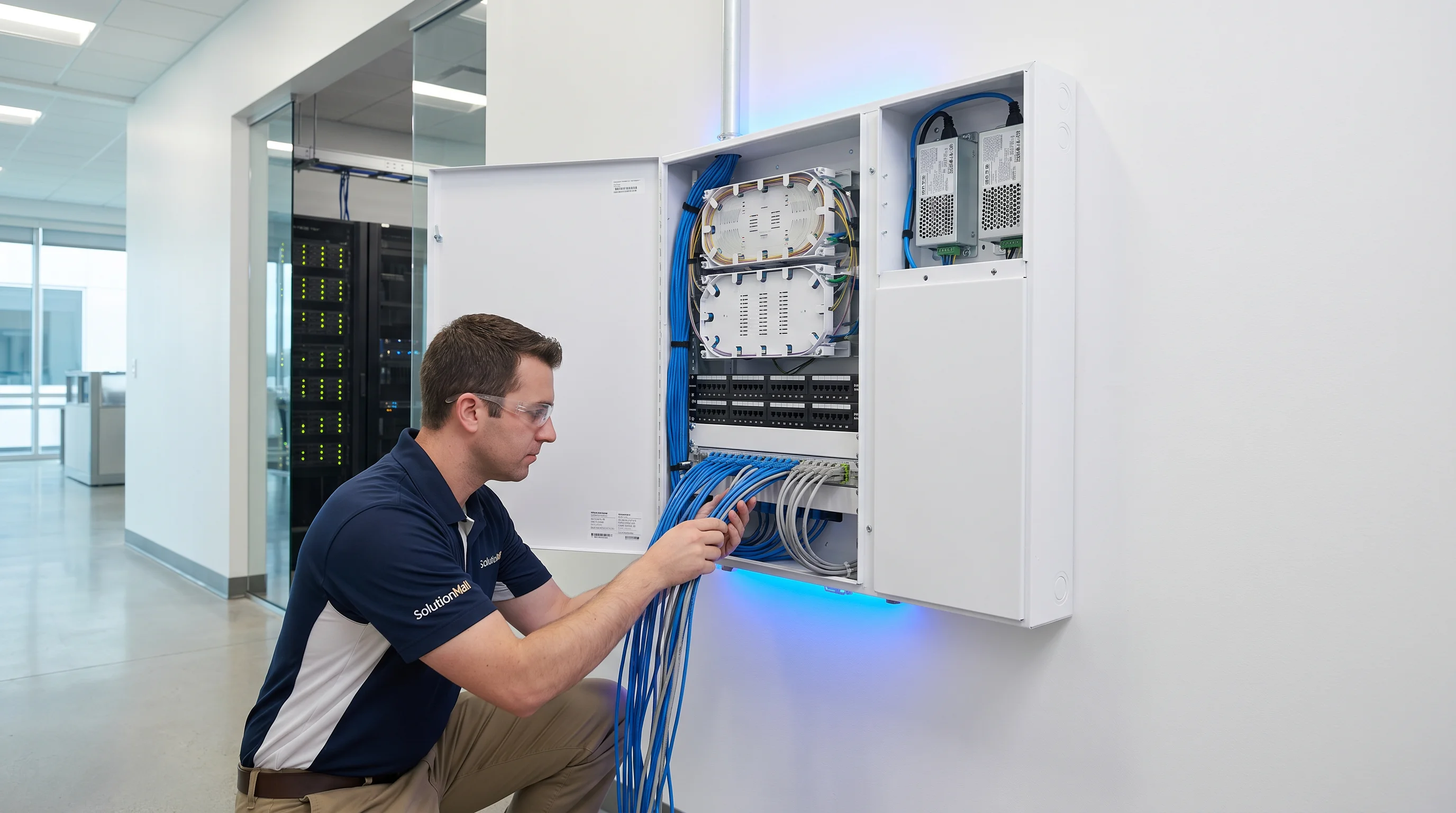
The Building Weak Current Information Box Solution establishes a structured, maintainable wiring node at each floor or unit level in modern buildings. Rather than simply providing a box to hide cables, this solution creates a proper information access point that supports multiple systems — network, fiber optic, telephone, cable TV, and access control — within a single organized enclosure.
In residential, commercial, hotel, hospital, and school projects, the information box is the critical junction between the building's backbone infrastructure and the end-user's devices. Poor implementation at this point leads to tangled wiring, difficult troubleshooting, and costly upgrades. A properly designed information box solution eliminates these problems through standardized patch panels, fiber termination modules, cable organizers, and clear labeling systems.
This solution is particularly valuable for projects transitioning from traditional copper-based infrastructure to fiber-to-the-unit (FTTU) architectures, as it provides the physical framework for both current and future connectivity technologies within the same enclosure.
Core Value Propositions
System Architecture Diagram
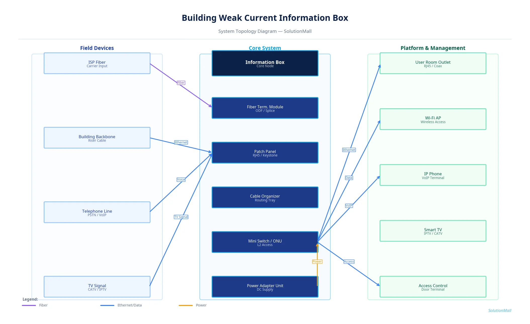
Building Weak Current Information Box Solution — System Topology Diagram by SolutionMall
Technical Specifications
| Box Type | Wall-mounted information distribution box |
| Protection Rating | IP30 (indoor) / IP54 (semi-outdoor) |
| Material | Cold-rolled steel, ABS plastic, or stainless steel |
| Dimensions | 300×400×120mm to 600×800×200mm (project-specific) |
| Mounting | Flush-mount or surface-mount, DIN rail inside |
| Port Capacity | 12 to 48 ports (patch panel), expandable |
| Fiber Capacity | Up to 24 fibers per termination module |
| Power | Optional 220V power strip for ONU/switch |
| Lock | Key lock, tamper-evident |
| Operating Temp | 0°C to +50°C |
System Modules
System Workflow
Backbone Cable Entry
ISP fiber or building backbone cable enters the information box through the cable entry point. Fiber cables are secured with cable clamps to prevent tension on the fiber core.
Fiber Termination
Fiber pigtails are fusion-spliced to the incoming fiber and routed through the splice tray to the adapter panel. Each fiber is labeled with its circuit ID.
Copper Cable Termination
Ethernet backbone cables are punched down to the patch panel following T568B standard. Each port is labeled with room/outlet number.
Active Equipment Connection
ONU or small switch is installed on the DIN rail bracket. Fiber patch cord connects the adapter panel to the ONU; Ethernet patch cords connect the patch panel to the switch.
Distribution to End Points
Patch cords from the switch or patch panel route to individual room outlets, Wi-Fi APs, IP phones, or access control terminals throughout the floor or unit.
Testing & Documentation
All links are tested with a cable tester or optical power meter. Port-to-room mapping is documented and attached inside the box cover for future reference.
Application Scenarios
Selection Guide
Deployment & Implementation Notes
Key Products Required
Why Choose SolutionMall
Engineering-Grade Quality
All enclosures and components meet IEC, ATEX, UL, and local standards. Rigorous quality control from material sourcing to final delivery ensures consistent performance across every project.
Fast & Reliable Delivery
Standard products ship within 3–7 business days. Custom solutions with 2–4 week lead time for most configurations. Global logistics network supports projects in 60+ countries.
Dedicated Technical Support
Experienced engineering team provides product selection guidance, system design review, BOM optimization, and on-site installation support for complex projects.
Global Supply Chain
Sourcing from 200+ qualified manufacturers across Asia, Europe, and North America. Competitive pricing with consistent quality and full traceability for every order.