Fiber Distribution & Cross-Connection Box Solution
← Back to Solutions Fiber Optic Infrastructure

Fiber Distribution & Cross-Connection Box Solution

Professional fiber distribution and cross-connection box solution for campus networks, FTTx deployments, and security backbone systems — ensuring low-loss, maintainable, and expandable optical fiber infrastructure.

ODF FTTx Splice Tray Low Loss Scalable

Solution Overview

The Fiber Distribution & Cross-Connection Box Solution addresses the most overlooked aspect of optical fiber networks: the quality of the termination and distribution nodes. While much attention is paid to fiber cable selection and active equipment, the long-term reliability of a fiber network is determined by how well the fiber connections are managed at each distribution point.

This solution provides a complete fiber management system — from incoming cable fixation and fusion splicing through splice tray organization, adapter panel termination, and patch cord management — within a properly designed enclosure. The result is a fiber distribution node with low insertion loss, high mechanical reliability, and clear traceability for maintenance and expansion.

Whether deployed as a campus backbone distribution node, an FTTx access point, a security system fiber hub, or an industrial fiber communication node, this solution transforms fiber connections from a vulnerability into a strength of the network infrastructure.

Core Value Propositions

Low Insertion Loss
Proper fusion splicing, bend radius management, and quality adapters maintain insertion loss below 0.3dB per connection — critical for long-distance and high-speed fiber links.
Mechanical Protection
Robust enclosure with cable strain relief, splice tray fixation, and fiber routing guides protect fragile fiber connections from mechanical damage.
Clear Traceability
Systematic fiber labeling, port numbering, and documentation enable rapid identification of any fiber circuit for maintenance, testing, or reconfiguration.
Scalable Capacity
Modular splice tray and adapter panel design allows capacity expansion from 12 to 144 fibers without replacing the enclosure.
Outdoor Durability
IP65 lockable outdoor enclosures with UV-resistant materials provide 20+ year service life for outdoor fiber distribution nodes.
Splitter Integration
Optional PLC splitter modules enable passive optical network (PON) splitting within the distribution box for FTTx deployments.

System Architecture Diagram

Fiber Distribution & Cross-Connection Box Solution System Topology Diagram

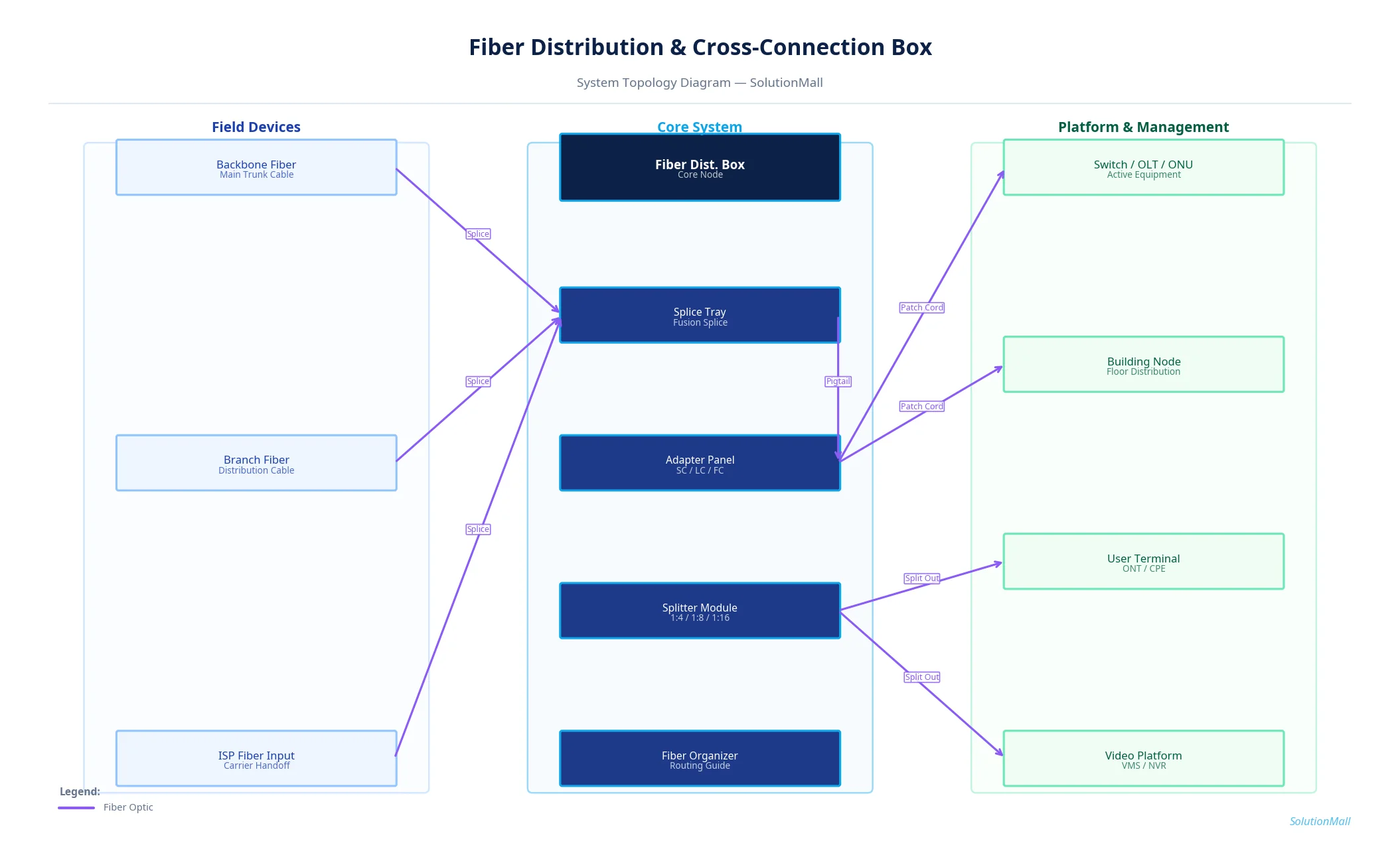
Fiber Distribution & Cross-Connection Box Solution — System Topology Diagram by SolutionMall

Technical Specifications

Box TypeWall-mount or pole-mount fiber distribution box
Protection RatingIP65 (outdoor) / IP20 (indoor)
MaterialABS plastic or cold-rolled steel
Dimensions300×200×120mm to 600×500×200mm
Fiber Capacity12 to 144 fibers
Splice Trays2 to 12 trays, 12 fibers per tray
Adapter TypesSC, LC, ST, FC (single or duplex)
Splitter Option1:2 to 1:32 PLC splitter module
Cable Entry2 to 6 cable entry ports with glands
Operating Temp-40°C to +70°C

System Modules

Splice Tray Module
Organizes fusion-spliced fiber pigtails with proper bend radius management, protecting splice points from mechanical stress and vibration.
Adapter Panel Module
SC/LC/ST adapter panels provide the interface between fusion-spliced pigtails and patch cords connecting to active equipment.
Splitter Module
PLC (planar lightwave circuit) splitter for passive optical network splitting, supporting 1:2 to 1:32 split ratios for FTTx deployments.
Cable Fixing Kit
Mechanical cable clamps and strain relief fittings secure incoming fiber cables and prevent tension from reaching the fiber cores.
Fiber Routing Accessories
Fiber routing guides, bend radius limiters, and velcro ties maintain proper fiber routing within the enclosure.
Labeling Module
Port identification labels, fiber circuit tags, and documentation holders for complete fiber traceability and maintenance records.

System Workflow

1

Cable Entry & Fixation

Incoming fiber cables enter the box through cable glands and are secured with mechanical clamps. The cable outer jacket is stripped back to expose the fiber buffer tubes, which are then routed to the splice tray.

2

Fiber Preparation & Splicing

Individual fiber cores are stripped, cleaned, and fusion-spliced to pre-terminated pigtails. Each splice is protected with a heat-shrink sleeve and placed in the splice tray holder.

3

Pigtail Routing to Adapter Panel

Spliced pigtails are carefully routed from the splice tray through fiber routing guides to the adapter panel, maintaining minimum bend radius throughout.

4

Adapter Panel Termination

Pigtail connectors are inserted into the adapter panel ports. Each port is labeled with the fiber circuit ID for traceability.

5

Patch Cord Connection

Patch cords connect the adapter panel ports to active equipment (OLT, ONU, switch, or media converter) or to downstream distribution boxes.

6

Testing & Documentation

Optical insertion loss is measured with an OTDR or optical power meter for each fiber circuit. Results are recorded in the fiber circuit documentation along with port assignments.

Application Scenarios

▶ FTTx Access Distribution
Deploy as the fiber distribution point for FTTH/FTTB/FTTC networks, managing the connection between feeder cables and drop cables to individual units.
▶ Campus Backbone Network
Serve as the inter-building fiber distribution node for campus networks, managing connections between backbone fiber and building entry points.
▶ Building Fiber Distribution
Provide floor-level or zone-level fiber distribution within commercial buildings, connecting backbone fiber to individual floor switches and APs.
▶ Security System Fiber Hub
Manage fiber connections for video surveillance backbone networks, connecting multiple camera aggregation switches to the central VMS server.
▶ Industrial Fiber Communication
Provide robust outdoor fiber distribution for industrial Ethernet networks connecting PLCs, SCADA systems, and field devices across large facilities.
▶ School Network Fiber Node
Deploy at campus building entry points to manage fiber connections between the campus backbone and building network equipment.

Selection Guide

✓ Determine fiber count (including future expansion) and splitter requirements before selecting box capacity — always specify 20% spare capacity.
✓ Outdoor deployments require IP65 or higher rated enclosures with UV-resistant materials and stainless steel hardware.
✓ High-density fiber projects need adequate splice tray space and fiber routing room — cramped boxes lead to bend radius violations and high insertion loss.
✓ If splitters are required, confirm split ratio and verify that the box has sufficient space for splitter modules and output fiber management.
✓ Front-access, swing-out designs are preferred for frequently maintained nodes — they enable fiber access without disturbing other connections.
✓ All fiber circuits should be documented with port assignments, splice records, and OTDR test results at the time of installation.

Deployment & Implementation Notes

⚠ Fiber cable fixation must be secure — mechanical tension must never reach the fiber cores through the splice or adapter connections.
⚠ Minimum bend radius must be maintained throughout the box — violations cause increased insertion loss and eventual fiber failure.
⚠ Fusion splice quality must be verified with an OTDR — splice loss above 0.1dB indicates a problem requiring re-splicing.
⚠ Fiber labels must be applied during installation — retroactive labeling is unreliable and creates long-term maintenance problems.
⚠ Outdoor box installation must prevent rain water ingress and unstable mounting — verify sealing and mechanical stability after installation.
⚠ Maintain complete fiber circuit records including splice locations, port assignments, and OTDR test results for future maintenance reference.

Key Products Required

Fiber Distribution Box / Cabinet Splice Tray Fiber Adapter Panel Pigtail / Patch Cord Splitter Module Cable Fixing Kit Fiber Routing Accessories Lockable Outdoor Enclosure Labeling Module

Why Choose SolutionMall

🏭

Engineering-Grade Quality

All enclosures and components meet IEC, ATEX, UL, and local standards. Rigorous quality control from material sourcing to final delivery ensures consistent performance across every project.

Fast & Reliable Delivery

Standard products ship within 3–7 business days. Custom solutions with 2–4 week lead time for most configurations. Global logistics network supports projects in 60+ countries.

🔧

Dedicated Technical Support

Experienced engineering team provides product selection guidance, system design review, BOM optimization, and on-site installation support for complex projects.

🌍

Global Supply Chain

Sourcing from 200+ qualified manufacturers across Asia, Europe, and North America. Competitive pricing with consistent quality and full traceability for every order.