Solution Overview
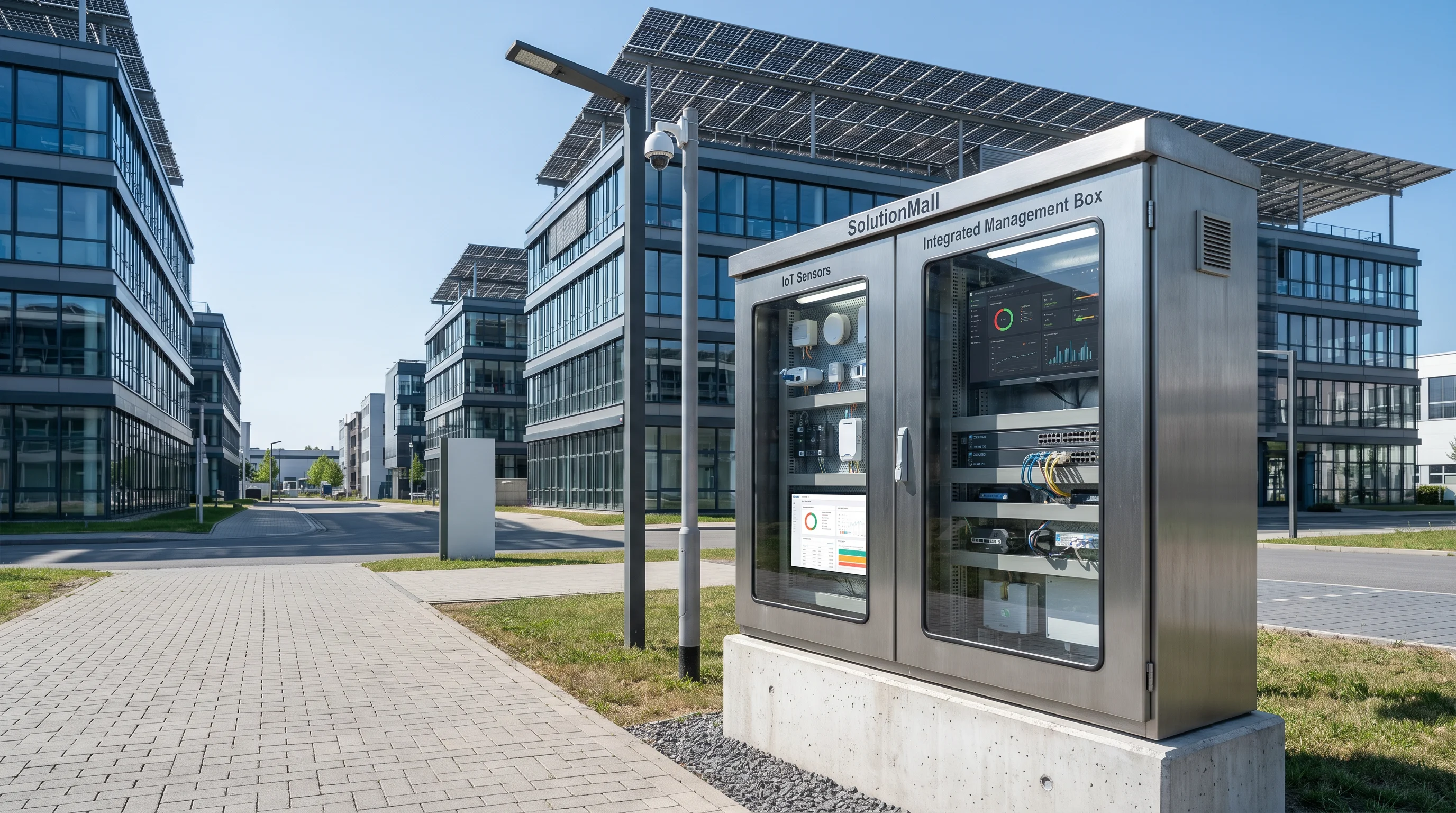
The Smart Park Integrated Box Solution addresses the fundamental challenge of modern smart park and campus deployments: how to unify multiple independent systems — video surveillance, access control, wireless network, environmental monitoring, and energy management — into a coherent, maintainable infrastructure at each field location.
Traditional approaches deploy separate boxes for each system, resulting in cluttered installations, redundant power supplies, inconsistent protection levels, and difficult maintenance. This solution consolidates all systems into a single engineered enclosure with proper power distribution, network switching, IoT gateway, and cable management — creating a unified field node that serves all systems simultaneously.
The integrated box approach is particularly valuable for smart park projects where multiple systems from different vendors must coexist and share infrastructure. By establishing a standard physical node, it simplifies project coordination, reduces installation time, and creates a maintainable foundation for long-term smart park operations.
Core Value Propositions
System Architecture Diagram
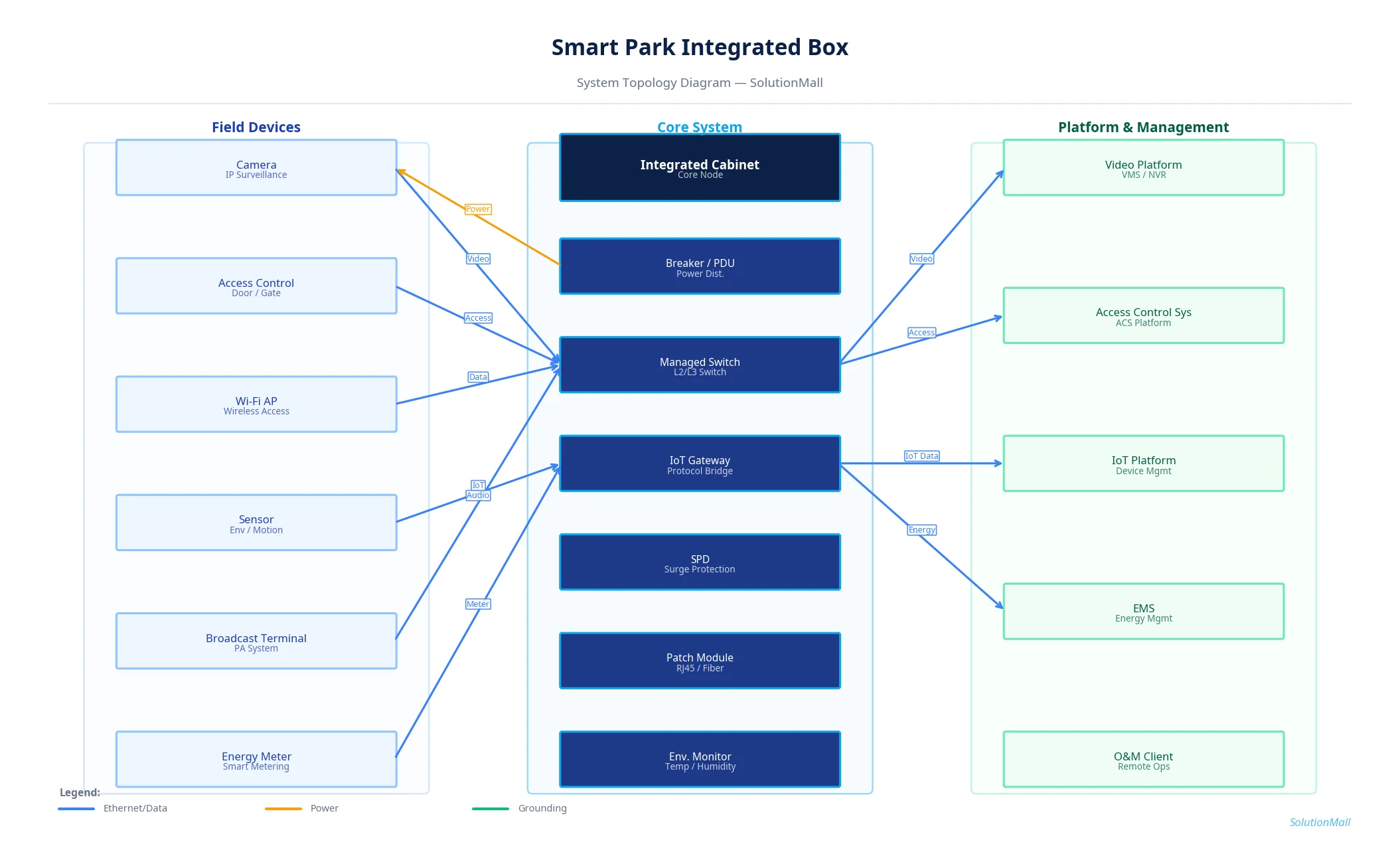
Smart Park Integrated Box Solution — System Topology Diagram by SolutionMall
Technical Specifications
| Box Type | Integrated smart park cabinet |
| Protection Rating | IP65 / IK10 |
| Material | 2.0mm cold-rolled steel, powder-coated |
| Dimensions | 800×600×300mm to 1200×800×400mm |
| Power Circuits | 8 to 24 output circuits |
| Switch Ports | 16 to 48 Ethernet + 4 SFP uplinks |
| IoT Gateway | Multi-protocol: Modbus, MQTT, BACnet, Zigbee |
| Power Input | AC220V / 380V |
| SPD | Power Type 2 + Ethernet SPD |
| Operating Temp | -30°C to +60°C |
System Modules
System Workflow
Multi-System Power Distribution
Grid power enters through the main breaker and SPD, then is distributed to individual circuits for cameras (PoE), access control (12V/24V), APs (PoE), sensors (5V/12V), and IoT gateway.
Network Data Aggregation
Cameras, APs, access control panels, and network-connected sensors connect to the managed switch. VLAN configuration separates traffic from different systems.
IoT Data Collection
Environmental sensors, energy meters, and access control devices connect to the IoT gateway via RS485, Modbus, or wireless protocols. The gateway normalizes data to MQTT or REST API format.
Platform Routing
Video data is routed to the VMS platform, access control data to the ACS platform, IoT data to the IoT platform, and energy data to the EMS — all through the managed switch's uplink.
Cabinet Health Monitoring
Internal temperature, humidity, door status, and power status are monitored by the environmental module and reported to the O&M platform for proactive maintenance.
Remote Management
All systems are accessible remotely through their respective management platforms. The managed switch provides network-level visibility for troubleshooting connectivity issues.
Application Scenarios
Selection Guide
Deployment & Implementation Notes
Key Products Required
Why Choose SolutionMall
Engineering-Grade Quality
All enclosures and components meet IEC, ATEX, UL, and local standards. Rigorous quality control from material sourcing to final delivery ensures consistent performance across every project.
Fast & Reliable Delivery
Standard products ship within 3–7 business days. Custom solutions with 2–4 week lead time for most configurations. Global logistics network supports projects in 60+ countries.
Dedicated Technical Support
Experienced engineering team provides product selection guidance, system design review, BOM optimization, and on-site installation support for complex projects.
Global Supply Chain
Sourcing from 200+ qualified manufacturers across Asia, Europe, and North America. Competitive pricing with consistent quality and full traceability for every order.