Solution Overview
The Industrial Automation Control Box Solution addresses the fundamental challenge of industrial automation: how to reliably organize, protect, and operate the control logic, electrical interfaces, and safety systems that govern machines, production lines, and process equipment. A control box is not simply a metal enclosure for a PLC — it is the engineered center of the entire control system.
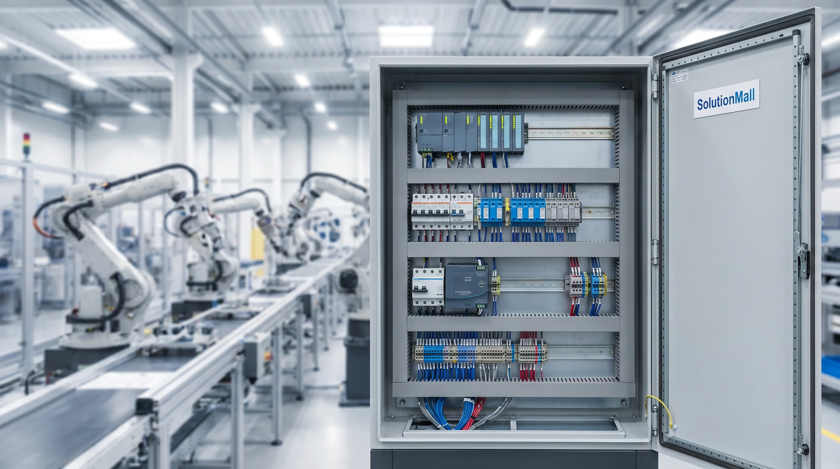
This solution integrates PLC controllers, I/O modules, relay and contactor systems, power supplies, circuit breakers, terminal blocks, and communication modules within a structured enclosure that meets industrial environmental requirements. The result is a control system that is stable, maintainable, expandable, and compliant with IEC 61439 and relevant industrial standards.
From simple pump control stations to complex multi-axis production line controllers, this solution provides the physical and electrical framework that transforms control logic into reliable machine operation. It is the foundation of every successful industrial automation project.
Core Value Propositions
System Architecture Diagram
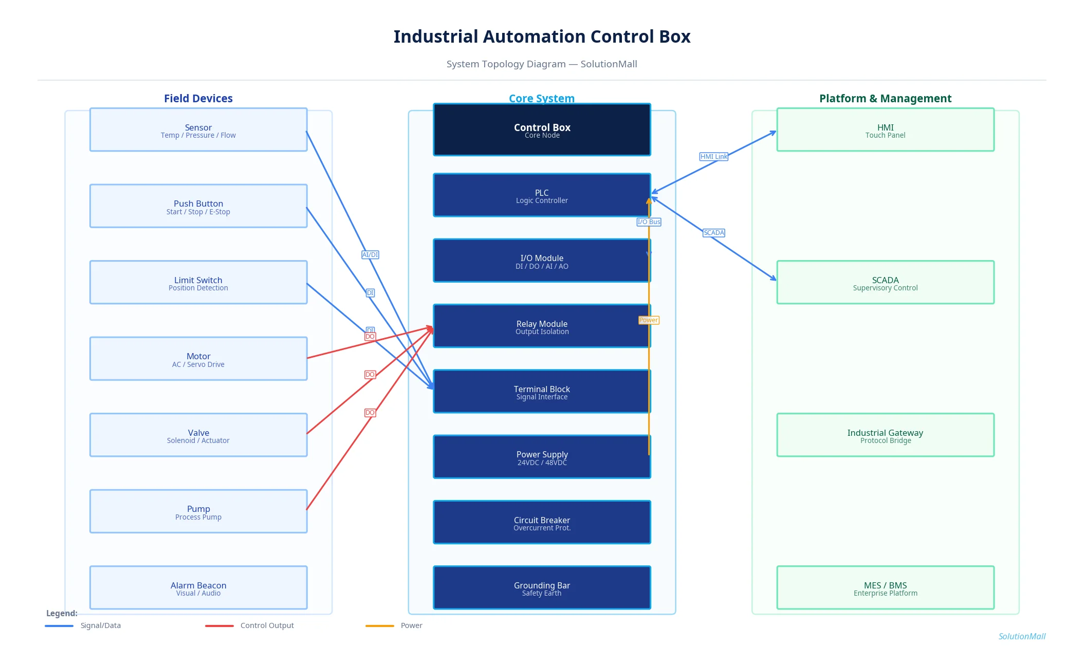
Industrial Automation Control Box Solution — System Topology Diagram by SolutionMall
Technical Specifications
| Box Type | Wall-mount or floor-standing industrial control box |
| Protection Rating | IP55 / IP65 (outdoor) |
| Material | 1.5–2.0mm cold-rolled steel, powder-coated |
| Dimensions | 600×800×250mm to 2000×800×600mm |
| DIN Rail | 35mm standard DIN rail, multiple rows |
| Power Supply | 24VDC / 48VDC internal power supply |
| PLC Compatibility | Siemens, Mitsubishi, Omron, Schneider, Allen-Bradley |
| Communication | Ethernet, RS485, Modbus, Profibus, PROFINET |
| Cable Entry | Bottom gland plate, EMC cable glands |
| Operating Temp | -20°C to +55°C |
System Modules
System Workflow
Field Signal Acquisition
Sensors, limit switches, push buttons, and pressure/temperature transmitters connect to the terminal block array and I/O modules. Digital signals are isolated through intermediate relays before entering PLC inputs.
PLC Logic Processing
The PLC CPU reads all input states, executes the control program, and determines output commands based on process logic, timing sequences, and safety interlocks.
Output Execution
PLC digital outputs activate relay coils, which in turn control contactors, motor starters, solenoid valves, and actuators. Analog outputs drive variable frequency drives and proportional valves.
Safety Circuit Operation
Emergency stop buttons, safety light curtains, and door interlocks are wired through dedicated safety relay circuits that bypass the PLC for immediate machine shutdown when triggered.
HMI & SCADA Communication
The PLC communicates with the local HMI panel via Ethernet or serial link, providing real-time process visualization and parameter adjustment. An industrial gateway bridges to SCADA or MES systems.
Alarm & Diagnostic Reporting
Fault conditions — overcurrent, communication loss, sensor failure — trigger alarm outputs and are logged in the PLC for maintenance review and SCADA notification.
Application Scenarios
Selection Guide
Deployment & Implementation Notes
Key Products Required
Why Choose SolutionMall
Engineering-Grade Quality
All enclosures and components meet IEC, ATEX, UL, and local standards. Rigorous quality control from material sourcing to final delivery ensures consistent performance across every project.
Fast & Reliable Delivery
Standard products ship within 3–7 business days. Custom solutions with 2–4 week lead time for most configurations. Global logistics network supports projects in 60+ countries.
Dedicated Technical Support
Experienced engineering team provides product selection guidance, system design review, BOM optimization, and on-site installation support for complex projects.
Global Supply Chain
Sourcing from 200+ qualified manufacturers across Asia, Europe, and North America. Competitive pricing with consistent quality and full traceability for every order.