Solution Overview
The Smart Meter Concentration Box Solution recognizes that the value of a metering system extends far beyond the accuracy of individual meters. The ability to collect, organize, and transmit metering data efficiently — and to maintain the metering infrastructure reliably over time — depends on the quality of the meter concentration node.
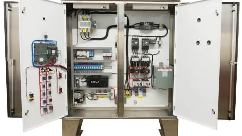
This solution provides a complete meter concentration box that centralizes multiple electricity, water, and heat meters in a single organized enclosure with standardized wiring, communication modules, and data concentrators. The result is a metering infrastructure that supports accurate billing, remote reading, energy management analytics, and long-term expandability.
As buildings and industrial facilities transition from manual meter reading to smart energy management systems, the meter concentration box serves as the critical physical node that bridges individual meters to digital energy management platforms. Proper design at this stage determines the success of the entire energy management system.
Core Value Propositions
System Architecture Diagram
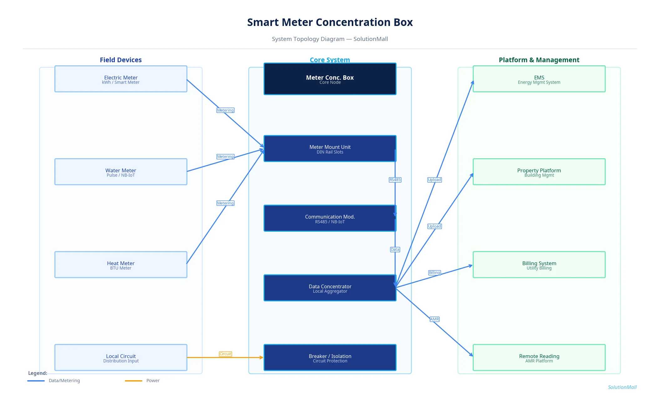
Smart Meter Concentration Box Solution — System Topology Diagram by SolutionMall
Technical Specifications
| Box Type | Smart meter concentration box / cabinet |
| Protection Rating | IP54 (indoor) / IP65 (outdoor) |
| Material | Cold-rolled steel or ABS plastic |
| Dimensions | 400×600×200mm to 800×1200×300mm |
| Meter Positions | 4 to 48 meter positions |
| Communication | RS485 / M-Bus / LoRa / NB-IoT / Ethernet |
| Power | AC220V for communication module |
| Sealing | Tamper-evident seals on meter connections |
| Lock | Key lock with access record |
| Operating Temp | -20°C to +55°C |
System Modules
System Workflow
Meter Installation & Wiring
Individual meters are installed in their designated positions within the concentration box. Power circuits (for electricity meters) or pipe connections (for water/heat meters) are connected according to the metering circuit diagram.
Communication Wiring
Meter communication ports (RS485, M-Bus, or pulse outputs) are connected to the communication module or data concentrator. Each meter is assigned a unique address for identification.
Data Concentrator Configuration
The data concentrator is configured with meter addresses, communication protocols, and reading intervals. Communication with each meter is verified before platform connection.
Platform Connectivity
The data concentrator connects to the EMS, property management platform, or utility billing system via Ethernet or cellular network. Data format and API compatibility are verified.
Automatic Meter Reading
The data concentrator automatically reads all meters at configured intervals (typically every 15 minutes to 1 hour) and transmits data to the management platform.
Billing & Analytics
The management platform processes meter data for billing calculations, energy consumption analysis, anomaly detection, and demand management reporting.
Application Scenarios
Selection Guide
Deployment & Implementation Notes
Key Products Required
Why Choose SolutionMall
Engineering-Grade Quality
All enclosures and components meet IEC, ATEX, UL, and local standards. Rigorous quality control from material sourcing to final delivery ensures consistent performance across every project.
Fast & Reliable Delivery
Standard products ship within 3–7 business days. Custom solutions with 2–4 week lead time for most configurations. Global logistics network supports projects in 60+ countries.
Dedicated Technical Support
Experienced engineering team provides product selection guidance, system design review, BOM optimization, and on-site installation support for complex projects.
Global Supply Chain
Sourcing from 200+ qualified manufacturers across Asia, Europe, and North America. Competitive pricing with consistent quality and full traceability for every order.