Solution Overview
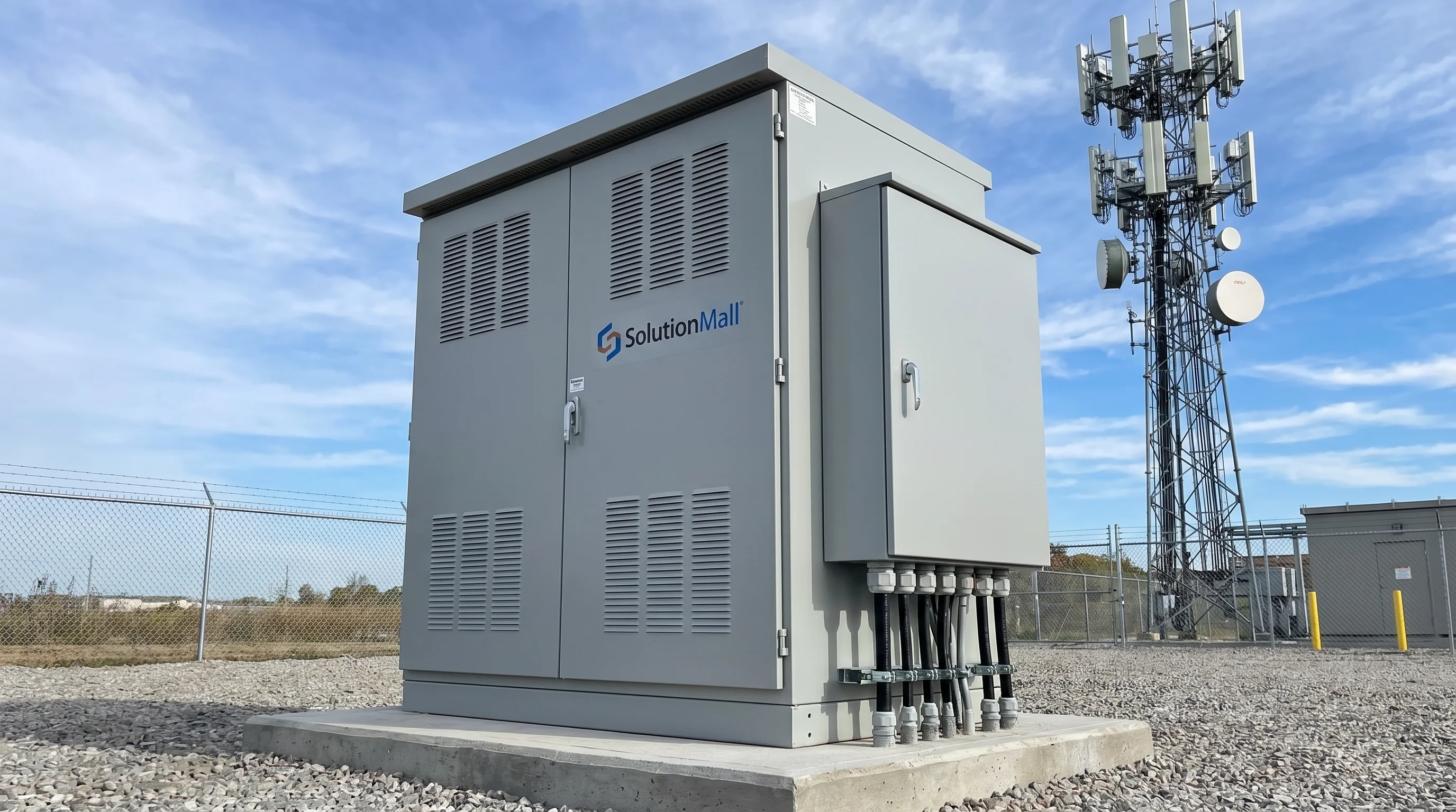
The Outdoor Telecom Access Cabinet Solution addresses the critical need for standardized, weatherproof communication nodes at the network edge. As networks expand beyond data centers and equipment rooms into outdoor environments — campus grounds, road infrastructure, industrial sites, and 5G edge locations — the quality of the outdoor access cabinet determines the reliability of the entire network segment.
This solution integrates optical distribution frames (ODF), industrial managed switches, DC power supplies, PDUs, surge protection devices, and cable management accessories within a robust outdoor cabinet. The result is a field communication node that provides the same level of organization, protection, and maintainability as an indoor equipment room — in any outdoor environment.
Whether serving as a campus network distribution node, a 5G edge computing site, or a fiber access point for a residential complex, this solution creates a standardized, scalable communication infrastructure that supports current requirements and future network evolution.
Core Value Propositions
System Architecture Diagram
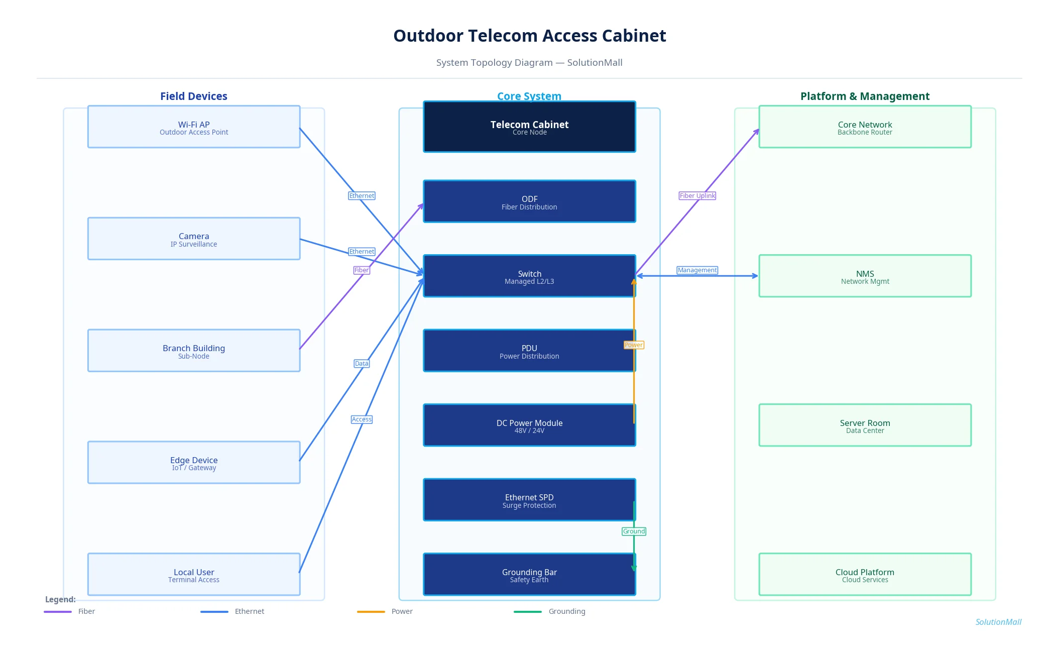
Outdoor Telecom Access Cabinet Solution — System Topology Diagram by SolutionMall
Technical Specifications
| Cabinet Type | Outdoor telecom access cabinet |
| Protection Rating | IP55 / IP65 |
| Material | 1.5mm cold-rolled steel, powder-coated |
| Dimensions | 600×600×1800mm to 800×800×2000mm |
| Rack Space | 12U to 24U, 19-inch standard |
| Power Input | AC220V with DC48V conversion |
| Fiber Capacity | 24 to 96 fiber ports (ODF) |
| Switch Ports | 24 to 48 Ethernet + 4 SFP uplinks |
| Cooling | Thermostat-controlled fan or heat exchanger |
| Operating Temp | -40°C to +65°C |
System Modules
System Workflow
Fiber Cable Entry & Termination
Incoming fiber cables enter the cabinet through bottom cable glands and are secured with cable clamps. Fiber cores are fusion-spliced to pigtails and routed through the ODF splice tray to the adapter panel.
Copper Cable Termination
Ethernet cables from field devices connect to the patch panel or directly to switch ports. All connections are labeled with circuit IDs for maintenance reference.
Network Switching & Aggregation
The managed industrial switch aggregates all field device connections and provides uplink connectivity to the core network via fiber SFP ports. VLAN configuration separates different traffic types.
Power Distribution
AC power enters through the main breaker and SPD, then is converted to DC48V by the rectifier for active equipment. Individual PDU circuits protect each device.
Uplink to Core Network
Aggregated network traffic is transmitted via fiber uplink to the campus core switch, data center, or cloud platform. Redundant uplink ports support failover configurations.
Remote Management
The managed switch provides SNMP-based remote monitoring of port status, traffic statistics, and equipment health. Alerts are sent to the NMS when faults are detected.
Application Scenarios
Selection Guide
Deployment & Implementation Notes
Key Products Required
Why Choose SolutionMall
Engineering-Grade Quality
All enclosures and components meet IEC, ATEX, UL, and local standards. Rigorous quality control from material sourcing to final delivery ensures consistent performance across every project.
Fast & Reliable Delivery
Standard products ship within 3–7 business days. Custom solutions with 2–4 week lead time for most configurations. Global logistics network supports projects in 60+ countries.
Dedicated Technical Support
Experienced engineering team provides product selection guidance, system design review, BOM optimization, and on-site installation support for complex projects.
Global Supply Chain
Sourcing from 200+ qualified manufacturers across Asia, Europe, and North America. Competitive pricing with consistent quality and full traceability for every order.