Solution Overview
The Video Surveillance Power & Access Box Solution recognizes a fundamental truth about surveillance system reliability: camera failures are rarely caused by the cameras themselves. The most common failure points are at the front-end power and access nodes — unstable power supply, inadequate surge protection, disorganized cabling, and poor weatherproofing.
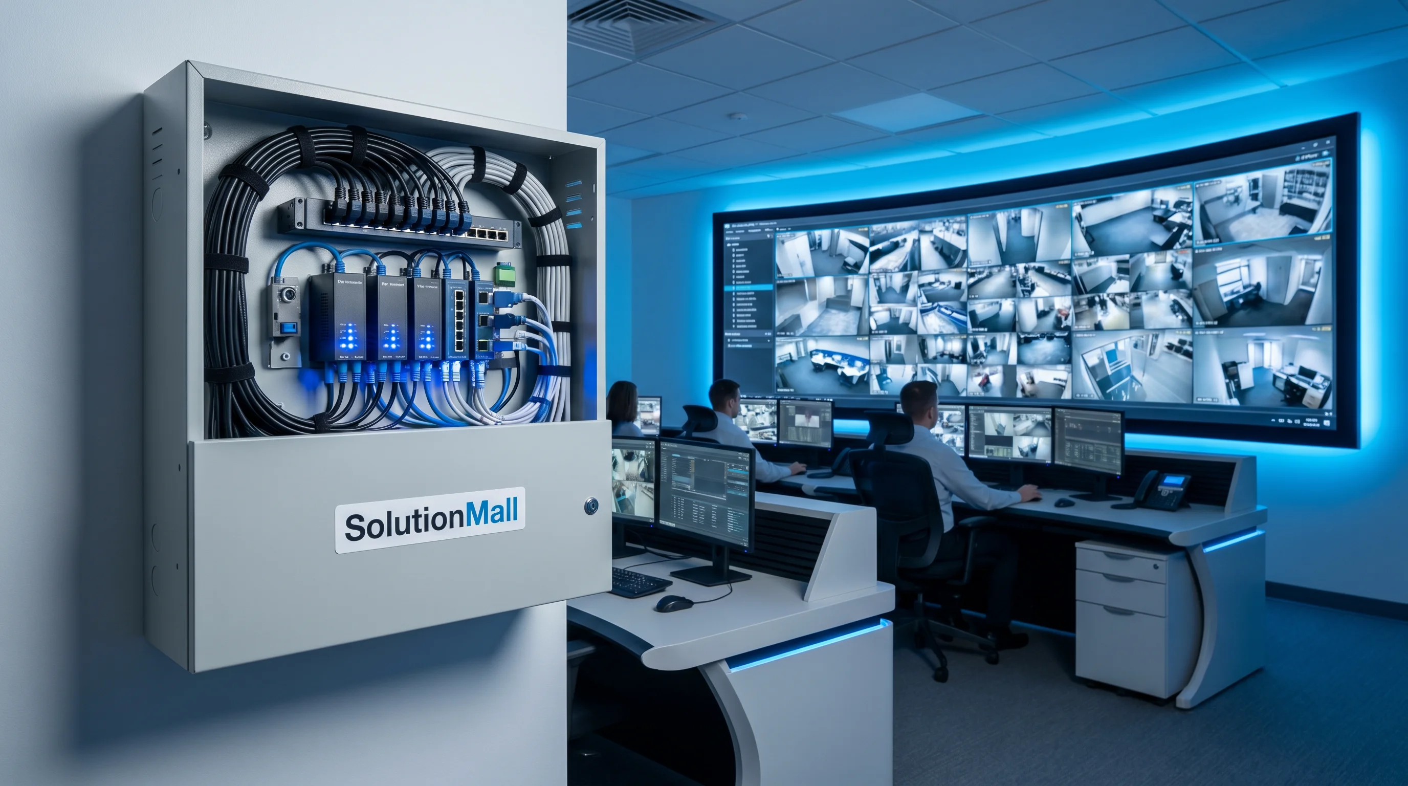
This solution integrates PoE switches, power modules, surge protection devices (SPD), terminal blocks, and cable management accessories within a weatherproof enclosure at each surveillance node. By standardizing the front-end access point, it transforms scattered, vulnerable camera connections into a reliable, maintainable, and expandable surveillance infrastructure.
Whether deployed on urban road poles, campus building walls, factory perimeter fences, or parking structure columns, this solution ensures that every camera in the system has stable power, protected network connectivity, and a structured physical installation that supports rapid maintenance and future expansion.
Core Value Propositions
System Architecture Diagram
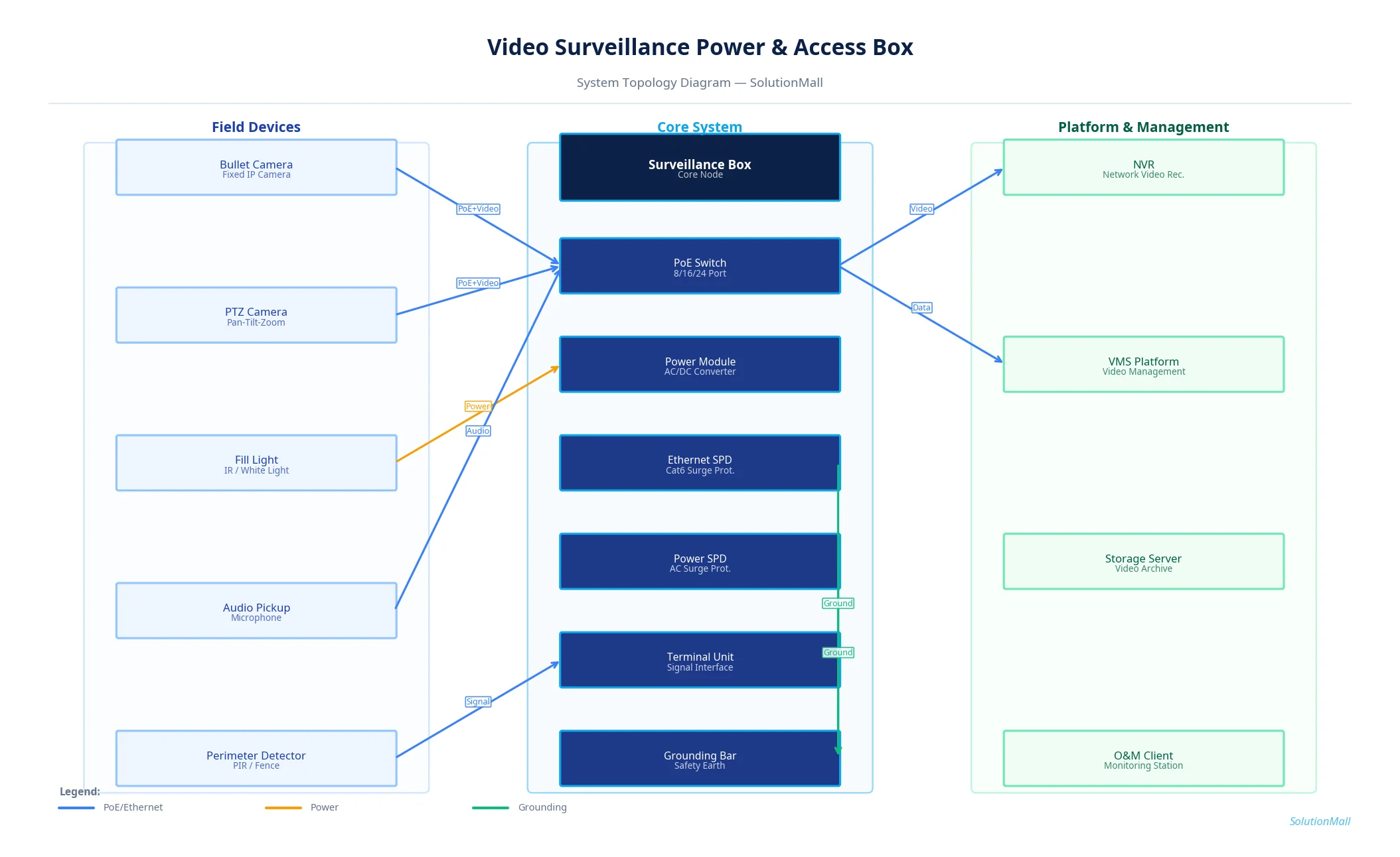
Video Surveillance Power & Access Box Solution — System Topology Diagram by SolutionMall
Technical Specifications
| Box Type | Wall-mount / pole-mount surveillance access box |
| Protection Rating | IP65 / IK08 |
| Material | 1.2mm steel or aluminum alloy, powder-coated |
| Dimensions | 400×500×200mm to 600×800×300mm |
| PoE Ports | 4 to 24 ports, 802.3af/at/bt |
| PoE Budget | Up to 400W total PoE output |
| Power Input | AC220V, 50/60Hz |
| SPD | Power Type 2 + Ethernet Cat6 SPD |
| Uplink | 2× Gigabit uplink ports (SFP or RJ45) |
| Operating Temp | -30°C to +60°C |
System Modules
System Workflow
AC Power Entry & Protection
Grid power enters the surveillance box through the main breaker and Type 2 power SPD. The power module converts and distributes power to the PoE switch and any non-PoE devices such as supplemental lighting.
Camera PoE Connection
IP cameras connect to the PoE switch ports via Cat6 cable. The switch simultaneously provides IEEE 802.3at/bt power (up to 30W/60W per port) and 1Gbps data connectivity to each camera.
Video Data Aggregation
Camera video streams are aggregated by the PoE switch and transmitted via the Gigabit uplink port to the NVR or VMS platform. The switch supports VLAN configuration for traffic management.
Surge Protection Path
All Ethernet connections pass through Cat6 SPD modules before reaching the switch ports. Any lightning-induced surge on the camera cable is safely diverted to the grounding bar and earth system.
Uplink to Backend Platform
The aggregated video stream is transmitted via fiber or Ethernet uplink to the NVR, VMS server, or cloud storage platform. Redundant uplink ports support failover configurations.
Remote Monitoring & Maintenance
The managed PoE switch provides SNMP-based remote monitoring of port status, power consumption, and camera connectivity. Alerts are sent to the O&M platform when cameras go offline.
Application Scenarios
Selection Guide
Deployment & Implementation Notes
Key Products Required
Why Choose SolutionMall
Engineering-Grade Quality
All enclosures and components meet IEC, ATEX, UL, and local standards. Rigorous quality control from material sourcing to final delivery ensures consistent performance across every project.
Fast & Reliable Delivery
Standard products ship within 3–7 business days. Custom solutions with 2–4 week lead time for most configurations. Global logistics network supports projects in 60+ countries.
Dedicated Technical Support
Experienced engineering team provides product selection guidance, system design review, BOM optimization, and on-site installation support for complex projects.
Global Supply Chain
Sourcing from 200+ qualified manufacturers across Asia, Europe, and North America. Competitive pricing with consistent quality and full traceability for every order.